The first thing that arrives on a Chicago retaining wall site is usually a track-mounted hydraulic drill rig, often a CME-75 or similar, setting up between the alley and the L-track right-of-way. Space is tight here—tighter than in most Midwestern cities—so mast clearance and utility mapping dictate the entire layout. Before any lateral earth pressure calculation begins, the crew logs the stiff, desiccated crust of the Blodgett till overlying the soft, normally consolidated Chicago clay, because that transition zone—usually between 8 and 14 feet below grade—controls whether a cantilever wall is even feasible. Where the clay is thicker, as it is east of Ashland Avenue, the slope stability of adjacent cuts becomes the governing check before wall geometry is finalized.
In Chicago’s glacial till, the drained friction angle can drop from 34° above the desiccation zone to 26° in the saturated clay—ignoring that shift can reduce wall safety factor below 1.5.
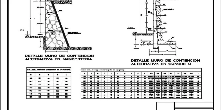
Local considerations
The contrast between Streeterville—built largely on granular lakefill with high permeability—and the inland neighborhoods west of the Kennedy Expressway, underlain by deep lacustrine clay, illustrates the risk spectrum in Chicago retaining wall design. In Streeterville, the primary concern is rapid drawdown behind a wall during dewatering, which can strip away the stabilizing water pressure and induce a sudden active wedge failure. West of the expressway, long-term consolidation settlement of the clay under the weight of the retained fill can rotate a rigid wall outward over months, cracking stair-step joints in block walls. Add the freeze-thaw cycling that Chicago experiences roughly 45 times per winter, and the upper 3 feet of backfill can swell laterally, exerting pressures well above Rankine predictions. A vibrocompaction treatment of the foundation zone or a granular chimney drain is often the difference between a wall that moves and one that stays plumb through five winters.
Applicable standards
ASCE 7-22 (Minimum Design Loads for Buildings and Other Structures), IBC 2021 / Chicago Building Code 2022 (Chapter 18: Soils and Foundations), FHWA GEC No. 2 (Earth Retaining Structures, 2017 revision), ACI 318-19 (Structural Concrete for Cantilever Walls), AASHTO LRFD Bridge Design Specifications, 9th Ed. (for walls along IDOT ROW)
Frequently asked questions
What is the typical cost range for retaining wall design in Chicago?
For a typical Chicago residential or light commercial retaining wall (4 to 12 ft exposed height), the structural and geotechnical design package ranges from US$1,010 to US$4,320. The final fee depends on wall height, proximity to neighboring foundations, whether the wall is within the Lake Michigan shoreline jurisdiction, and whether a separate geotechnical boring program is already available.
Does Chicago require a permit for retaining walls?
Yes. The Chicago Department of Buildings (DOB) requires a building permit for any retaining wall over 4 feet in height measured from the bottom of the footing to the top of the wall, or any wall supporting a surcharge (such as a driveway or building). Walls under 4 feet without surcharge may still require a permit if located in the public right-of-way. All permit applications require signed-and-sealed structural drawings and a geotechnical report from an Illinois-licensed professional engineer.
What soil parameters control retaining wall design in Chicago?
The drained friction angle (φ’) and cohesion intercept (c’) of the Blodgett till and Chicago clay are the primary parameters, obtained from consolidated-undrained triaxial tests with pore pressure measurement. For the upper desiccated crust, φ’ typically ranges from 32° to 36°; for the saturated Chicago clay below, φ’ drops to 24°–28°. Undrained shear strength from field vane or UU triaxial is used for short-term stability during excavation. Unit weight ranges from 120 to 135 pcf depending on sand content.
How long does the design process take for a Chicago retaining wall?
For walls up to 15 feet in height where a geotechnical report already exists, the design, detailing, and preparation of signed-and-sealed plans typically takes 2 to 3 weeks. If new borings are required—which is common in Chicago due to the variability of the till surface—add approximately 2 weeks for field work and laboratory testing. Expedited review through the DOB Self-Certification Program can reduce permit turnaround time.
What type of backfill is recommended behind retaining walls in Chicago?
We specify IDOT CA-7 (1-inch minus) or CA-6 crushed limestone, placed in 8-inch lifts and compacted to 95% of maximum dry density per ASTM D1557. A minimum 12-inch-wide granular chimney drain or prefabricated drainage composite is required behind the wall to prevent hydrostatic pressure buildup from Chicago’s frequent rain events and spring snowmelt. Free-draining backfill is especially critical in areas east of the Continental Divide where groundwater recharge is rapid.